We now carry a motion-activated module that is pre-assembled and you can see it at this link: Motion activated playback module
June 3, 2011
A few weeks ago a customer asked me about building a motion-activated switch that could play a message when someone walked past. Because this wasn't the first time someone had asked me for this, I went busy to work out a solution. At first, I was just going to use an Arduino and code up a solution, but as I thought about it a simpler solution presented itself. I grabbed a few of our kits from the self and started splicing them together. The result was quite satisfying.
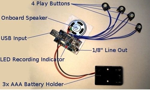
The base of the project is a recording module. In this situation, I used our USB5M 300 Second USB recording module, but any of the following will work with some simple wiring changes:
USB2M
USB5M
BD43
Or get our new USB6M+PIR here which has a light sensor and PIR ready to plug in!
After you get a message on your recorder, you can set it aside and move on to the next step.
After you get a message on your recorder, you can set it aside and move on to the next step.
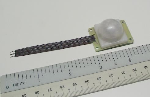
The next component in the module is the PIR. A PIR or Passive Infrared detector measures infrared light radiating from an object in its field of view. Since living things naturally give off infrared radiation, the PIR will detect a passing person. This will also work with dogs, cats, or anything else that is living and of substantial size, (most insects are excluded). The PIR I chose was the PIR383E . I picked it because of its small size, relatively simple operation, and it has a really neat "start-up" delay that prevents it from triggering in the first 25 seconds.
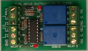
Now, I have the sound recorder and my PIR but there is still a major problem. The playback module uses a simple normally open momentary switch to activate. The PIR's output is a digital high-low signal. These two interfaces are incompatible. Fortunately for the electronics hobbyist, we have a solution. The CPS156 is a dual-channel HI /LO switch. Basically, it takes a HI / LO digital signal, processes it, and then decides whether or not to switch a mechanical switch (relay). I assembled a CPS156 (which only took about 15 minutes) and now I was ready to bring everything together.
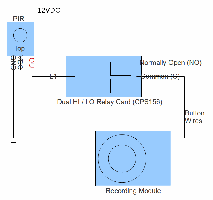
NOTE: The above diagram only triggers relay #1 to which the recording module is attached. You can also use relay #2 to trigger another device (say a light bulb that must light up at the same time that the sound is played back). In that case you will also wire the OUT connection of the PIR to the L2 input of the CPS156 and then attach your light bulb to relay #2. (Please see this link for the proper way to connect a load to a relay)
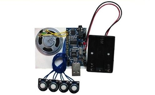
The wiring is relatively simple and because the CPS156 and BB054 use the same voltage, they can operate off of the same power supply. Above is a wiring diagram and below are some pictures of the finished product.
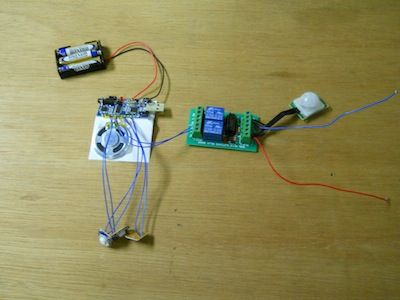
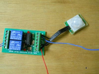
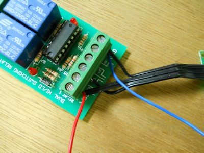
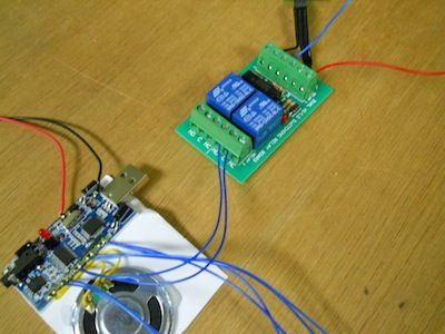
The PIR only has three connections that need attaching and they are relatively straightforward. The recording module will likely have a "play" button attached via two wires. You will need to cut the two wires and remove the button. These two wires will then attach to the relay output on the CPS156. Once everything is wired up attach your power supply. You will notice that for the first 25-30 seconds nothing happens. This is the start-up delay. After the startup delay is complete, walking past the PIR will activate the relay and play the message back.
-Tanner Ewing
VP of Engineering