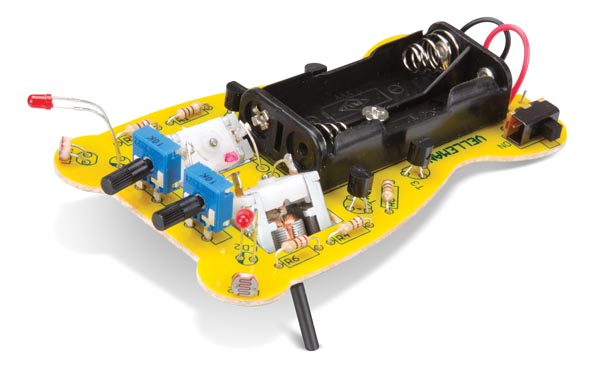
Description: Have fun building the Running Microbug minikit and watching it run towards the light. The DIY minikit circuit is built using general purpose transistors, fixed resistors, potentiometers and light sensitive resistors. These components are used to amplify and supply current to the miniature dc motors that allow the Velleman microbug to run. The circuit also has red LEDs that light when the motors are running, indicating the direction of travel. Use the potentiometers to adjust the light sensitivity. The MK127 is designed to stop in total darkness.
Features:
Two open chassis sub-miniature motors
adjustable light-sensitivity suits almost any light condition and allows to control it's 'bug-like' behavior
LED 'eyes' indicate driving direction
stops in total darkness
| Technical Data | |
| Specifications | power supply: 2 x 1.5V AAA batteries (not incl.) |
| Operational Properties | |
| Instruction Manual Languages | Dutch, English, French, German, Italian, Polish, Portuguese, Spanish |
| Product Basic Info | |
| Color | Yellow |
| Depth | 100 mm |
| Width | 60 mm |
| Weight | 69 g |
| Skill Level | |
| Coding Skill Level | 2 |
| Electronics Skill Level | none |
| Mechanics Skill Level | none |
| Soldering Skill Level | 2 |
Note:
To our valued customers:
It has been brought to our attention that some batches of MK127/MK129 might contain motors with different polarity indications than the ones mentioned in the manuals.
Two types are available:
Motors, where the '+' is indicated by a plus-sign in a circle.
Motors, with a red mark close to one of the connections. This mark indicates the MINUS of the motor.
Future manuals will feature instructions for both types of motors.
If you have any doubt, you can check the sense of rotation by applying 1.5..3V to the motor, using the supplied battery connector and observe the sense of rotation.
Sorry if this has caused any confusion.
Documentation and Downloads


